

I figured questions are always asked about how to install an aftermarket HU on our cars and I was installing a new HU in my girl's :b55: Why not do a write-up. Here it is:
Single DIN
![Image]()
Double DIN
![Image]()
From what my experience most :b5:'s had Single DIN and most :b55:'s had Double DIN. I am not exactly sure when the transition was made from Single DIN to Double DIN.
The install is the same if you have Monsoon or non-Monsoon. Many Car audio shops and Electronics Stores will try and tell you otherwise, but whether it is to milk more money out of you or utter ignorance, it is NOT TRUE. The install is THE SAME.
Now we will start off with everything you will need
Supplies
Tools
Procedure
Here are some basics of 12volt electrical connections
Now that we have our mis en place, lets get started. Not out to the car just yet. First take the Wiring harness and Install Instructions out of the box of your new HU. It should look like this:
![Image]()
grab your Wiring harness adapter, Antenna Adapter (You need this now if you have the Double DIN), Butt Connectors, Wire Crimping Tool, and Wire stripper.
Now there are, usually, standard wire colors for the wiring harnesses.
RED Wire = 12 Volt Iginition/Accessory (Switched)
Yellow Wire = 12 Volt Battery/Memory (Constant)
BLACK Wire = Ground
BLUE Wire w/ WHITE Stripe = Amp Turn On
BLUE Wire = Power Antenna
ORANGE Wire = Illumination
ORANGE Wire w/ WHITE Stripe = Dimmer
GRAY Wire = Right Front (+)
GRAY Wire w/ BLACK Stripe = Right Front (-)
WHITE Wire = Left Front (+)
WHITE Wire w/ BLACK Stripe = Left Front (-)
PURPLE Wire = Right Rear (+)
PURPLE Wire w/ BLACK Stripe = Right Rear(-)
GREEN Wire = Left Rear (+)
GREEN Wire w/ BLACK Stripe = Left Rear(-)
Note:There may be 2 Yellow Wires coming from your HU's Wiring Harness. I simply connected both of those wires to the ONE yellow of the Wiring harness adapter.
The new HU's Wiring harness will match the Metra Wiring Harness Adapter, but there are a few modifications that you will want to do if you want the new HU to function similarly to the Factory HU.
*IMPORTANT* There will be corresponding wires on the Wiring harness adapter. DO NOT simply butt connect the above wires to the adapter. Simply tape off those wires on the wiring harness adapter, as they will not be used.
There are other wires from the HU's Wiring harness that may not be used. Here are some examples:
*If they are not used simply tape them off until they are used
Now that your wiring is complete it should look something like this

Click Picture to enlarge
As you can see in the pic I do have the Amp Turn On wire (remote wire) ready for install, but I don't have the Switched 12V and Illumination Wires prepped. (Well, all of you get to benefit from my mistake in lack of preparation). You may also notice that I opted to use solder and heat shrink (that is what I had on hand), butt connectors will work just as well and should be easier to work with.
Now we need to create the Radio Removal Tools. On here it is commonly done by modifying a hanging file folder. This probably is the most cost effective way. Cut them any way you know how. I used a dremel, but I am sure you can use tin snips or those fancy scissors that can cut through a penny. If you bought the radio removal tools you can skip this step.
We are now ready to move this party out to the car.
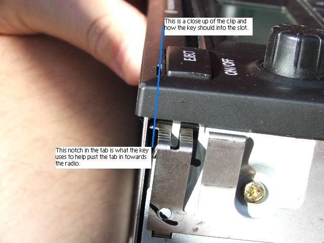
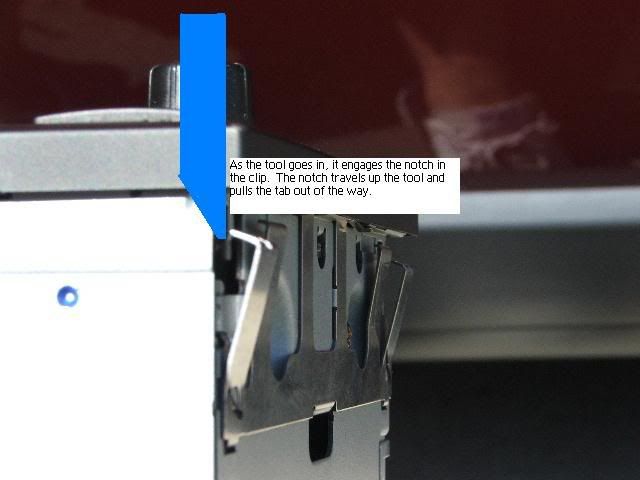
You will now notice four slots in each corner of the factory HU.
![Image]()
Can you guess what goes into those four slots. That's right the four tools you made from the hanging file. Here is the orientation of those tools in the slots.
![Image]()
![Image]()
![Image]()
![Image]()
![Image]()
![Image]()
Once the tools are inserted about and inch and a half you can gently stick your fingers in the cassette hole and slide the HU out.
If you bought the tools you insert them in the same fashion, but chances are if you only bought one set you only have a pair of tools as opposed to the four needed. Don't fret though. You can do one side at a time.
Now it should look like this:
![Image]()
Now remove the tools and you will have something that looks like this
![Image]()
Note: If you are weary of doing this part on your own, you can drive to the dealer and they should easily be able to pull the HU out for you (usually for free) and you can drive home with the HU sticking out like the picture above.
Now with the HU pulled completely out you will see two connections to the back of the factory HU
First we will remove the antenna connection. I am sure you can figure it out, but simply push on the tab and pull the plug out.
![Image]()
Now we will remove the Factory Wiring harness
Here is a pic of the Harness as you see it with the Attachment bar down
![Image]()
You want to lift the attachment bar to the up position as seen here
![Image]()
Now you can simply pull the plug out.
This is similar to what it should look like:
![Image]()
Now you can match the Wiring harness adapter to the Factory Wiring harness as seen here:
![Image]()
Note: When first inserting the plug make sure the attachment arm is up because the arm down is the "Locked In" position. As you insert the plug the arm will come down and you will lock the plug in place by fully depressing the arm.
Seen here locked in place:
![Image]()
Now we will work on the antenna
Now for those last two wires, and unfortunately the more time consuming
We need to to remove the lower dash on the driver's side. Here is how you do it.
First you need to remove the headlight switch. For those who don't know how here is a quick rundown how to do it.
Here is it what it looks like in the "off" position
![Image]()
Here is what it looks like pushed in, in the "off" position. You want to push it in and then turn clockwise and you will hear it release
![Image]()
Here is what it looks like pushed, turned clockwise, and pulled out
![Image]()
Once it is out you push the tab and pull out the plug as seen here:
![Image]()
Now you need to remove the fuse panel cover like so:
![Image]()
![Image]()
Now to remove the lower dash panel you need to remove 4 torx screws (some Torx 20 , some 25) pictured here
![Image]()
![Image]()
Now that the screws are out the lower dash is held in by some clips. A nice little tug on the lower dash will release them and it should look a little like this now:
![Image]()
Note:Once you pull the lower Dash free there may be a couple of wires/cables that you may want to disconnect due to their short length to make things easier. Sorry I don't have any pics. Just remember when you unplug something remember how and where it plugs back in. Take a picture if you need to. The two other cables you may need to disconnect:
Note:Now would be a good time to disable you daytime running lights (DRL) if you are so inclined. Simply remove relay 173 as seen above and circled below.
![Image]()
Now with the Lower dash removed access is a lot easier. Now you can feed the two 5 ft 16 gauge wires for 12V Switched and Illumination through here
![Image]()
and they should come out around here
![Image]()
You may have to fish around a little, but they will come through there. Make sure you know which wire is Illumination and which is for switched 12V.
First we will work with the illumination wire
Remember the plug that went into the headlight switch? Find that Plug. It looks like this
![Image]()
Notice that I have circled the GRAY wire with a BLUE stripe. This is the wire you will be tapping for illumination.
Use one of the wire taps and connect the Illumination wire to it like this
![Image]()
Note:The Scotch-Locks or wire taps seen here have been known to not make the best connection. To ensure a good connection:
Illumination DONE
Next is the 12V Switched. There are a couple of places where you can tap this.
1st would be the switched 12V Bolt (75X) under the dash here
![Image]()
Simply strip the end of the wire and screw into the contact.
This method will turn on the HU when the key is in the "on" position. This is the easier of the two method but is less like factory.
The second method is a little more difficult, but this will allow you to use the HU until the key is removed from the ignition. Much more like stock. Here you will be tapping, what I believe is called the S-contact (correct me if I am wrong) This is tapped at the tach cluster plug seen here:
This is the view from the fuse panel on the side
![Image]()
This is the view from under the dash
![Image]()
IMPORTANT: DO NOT have the key in the ignition in any way at this point. The key should not be in the ignition until you have completed working with the tach cluster plug and replaced it in its proper place. Doing so will result in a CEL that cannot be removed except by VAG-COM.
Now remember how you lifted the arm to release the wiring harness from the factory hu? This releases in a similar fashion. you will be lifting the PINK arm and pulling the plug out like so:
![Image]()
The arm may be a little sticky, but I assure you it does go up.
Now you can pull down the plug to work with. It should look like this:
![Image]()
As you can see I have circled the RED wire which we will be tapping similar to the Illumination wire.
Note:Again, as stated when doing the Illumination wire, he Scotch-Locks or wire taps seen here have been known to not make the best connection. To ensure a good connection:
This is what it should look like after tapping the wire:
![Image]()
Now replace the plug and lock it down by depressing the arm.
You are now DONE with the wiring. Re-assemble the lower dash opposite from the way that you disassembled it.
Some tips when putting it back togther
Almost done...
Now back to the Radio hole.
These are what some of my parts looked like.
![Image]()
First you want to tuck most of the wiring into the back of the hole, so just enough is sticking out to make the connections to the HU. Like this
![Image]()
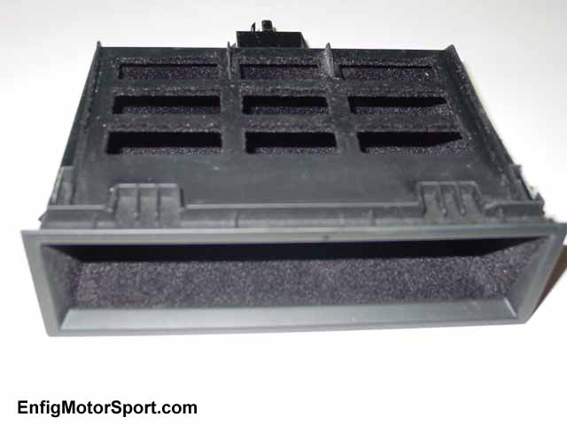
Next you want to insert the Pocket
![Image]()
The order is important here. Make sure you do put in the pocket before the cage/sleeve
When getting ready to insert the sleeve make sure that all of the wiring is coming through the sleeve. Like this
![Image]()
Now insert the sleeve fully and then you will bend tabs on the sleeve to make sure the HU stays in the dash. (The HU locks into the sleeve)
![Image]()
Push in the tabs after the sleeve has been pushed all the way in.
Now plug all the proper plugs into the back of the HU. Basically just the Antenna and the Wiring harness. You want make any RCA connections (if any) at this time as well. Like this
![Image]()
Now that all of the connections are made, slide the HU into the sleeve and push back until you hear a "click" of the sleeve locking in the HU. the only thing you should be left with is the trim ring. Slide it over the HU in the proper orientation and enjoy a job well done.
Before
![Image]()
After
![Image]()
![Image]()
If you have any question please post in the thread (Don't PM me), so that others may be able to help and so others may learn from your question as well.
If you find any mistakes in this or feel that I should make an addition to this post, please DO PM me and I will make the Appropriate changes. I hope this helps others, as I have been help through this site. Good Luck.
If you can't figure out why none of the electrical is working on your car. Try re-connecting the negative terminal on your battery. I know I forgot to write it in.
HERE is a link to the picture album where all of the pics to the install are hosted. The pictures are labeled. Hope it helps with some of the picture problems.
If anyone is still having problems with the pictures after that. PM me your email address and I can email you the post in Word format.
thad.
Just to clarify know what is Double DIN and Single DIN
Single DIN

Double DIN

From what my experience most :b5:'s had Single DIN and most :b55:'s had Double DIN. I am not exactly sure when the transition was made from Single DIN to Double DIN.
The install is the same if you have Monsoon or non-Monsoon. Many Car audio shops and Electronics Stores will try and tell you otherwise, but whether it is to milk more money out of you or utter ignorance, it is NOT TRUE. The install is THE SAME.
Now we will start off with everything you will need
Supplies
- Head Unit of your choice (I chose to go with a Clarion DXZ665MP)

- Single DIN Pocket - used only if you have a Double DIN and are Going to a Single DIN aftermarket HU

- Radio Wiring Harness
I will give you Metra part numbers for Double DIN and Single DIN- Double DIN Metra Part # 70-9003
![Image]()
- Single DIN Metra Part # 70-1784
![Image]()
- Double DIN Metra Part # 70-9003


- Antenna Adapter
- Double DIN Metra Part # 40-EU55
![Image]()
- Single DIN
- Double DIN Metra Part # 40-EU55


- Some Extra Wire


- Hanging File Folder to make a radio removal tool
![Image]()
Or you can buy these


Tools


- Trox 20 (T20) Screwdriver
- Torx 25 (T25) Screwdriver
Procedure
Here are some basics of 12volt electrical connections
Now that we have our mis en place, lets get started. Not out to the car just yet. First take the Wiring harness and Install Instructions out of the box of your new HU. It should look like this:

grab your Wiring harness adapter, Antenna Adapter (You need this now if you have the Double DIN), Butt Connectors, Wire Crimping Tool, and Wire stripper.
Now there are, usually, standard wire colors for the wiring harnesses.
RED Wire = 12 Volt Iginition/Accessory (Switched)
Yellow Wire = 12 Volt Battery/Memory (Constant)
BLACK Wire = Ground
BLUE Wire w/ WHITE Stripe = Amp Turn On
BLUE Wire = Power Antenna
ORANGE Wire = Illumination
ORANGE Wire w/ WHITE Stripe = Dimmer
GRAY Wire = Right Front (+)
GRAY Wire w/ BLACK Stripe = Right Front (-)
WHITE Wire = Left Front (+)
WHITE Wire w/ BLACK Stripe = Left Front (-)
PURPLE Wire = Right Rear (+)
PURPLE Wire w/ BLACK Stripe = Right Rear(-)
GREEN Wire = Left Rear (+)
GREEN Wire w/ BLACK Stripe = Left Rear(-)
Note:There may be 2 Yellow Wires coming from your HU's Wiring Harness. I simply connected both of those wires to the ONE yellow of the Wiring harness adapter.
The new HU's Wiring harness will match the Metra Wiring Harness Adapter, but there are a few modifications that you will want to do if you want the new HU to function similarly to the Factory HU.
- The BLUE Power Antenna wire on the HU's wiring Harness will be attached to the blue wire on the Antenna adapter using a butt connector
- The ORANGE Illumination wire on the HU's wiring Harness will attach to 5 ft. of the 16 gauge wire, to be tapped elsewhere later in the install
- The RED12 Volt Iginition/Accessory (Switched) wire on the HU's wiring Harness will attach to the other 5 ft. of 16 gauge wire, again, to be tapped elsewhere later in the install
*IMPORTANT* There will be corresponding wires on the Wiring harness adapter. DO NOT simply butt connect the above wires to the adapter. Simply tape off those wires on the wiring harness adapter, as they will not be used.
There are other wires from the HU's Wiring harness that may not be used. Here are some examples:
- BROWN Wire = Phone Mute - may be used later if you have a mobile phone kit (i.e. Clarion BT-1)
- BLUE wire with White stripe = Amp Turn On - may be used later if installing an external amplifier for a subwoofer or after market speakers
- There, often times, will be RCA Cables coming from the back of the HU which are only typically used for external amplification or AUX input. They will not be used for the purposes of this install
*If they are not used simply tape them off until they are used
Now that your wiring is complete it should look something like this

Click Picture to enlarge
As you can see in the pic I do have the Amp Turn On wire (remote wire) ready for install, but I don't have the Switched 12V and Illumination Wires prepped. (Well, all of you get to benefit from my mistake in lack of preparation). You may also notice that I opted to use solder and heat shrink (that is what I had on hand), butt connectors will work just as well and should be easier to work with.
Now we need to create the Radio Removal Tools. On here it is commonly done by modifying a hanging file folder. This probably is the most cost effective way. Cut them any way you know how. I used a dremel, but I am sure you can use tin snips or those fancy scissors that can cut through a penny. If you bought the radio removal tools you can skip this step.
- Here is what you start off with:
![Image]()
- Now you need to remove the metal hanger parts:
![Image]()
- Now you want to cut each of them in half on a bias like this:
![Image]()
- You should now have four angled pieces

We are now ready to move this party out to the car.
You will now notice four slots in each corner of the factory HU.

Can you guess what goes into those four slots. That's right the four tools you made from the hanging file. Here is the orientation of those tools in the slots.


Once the tools are inserted about and inch and a half you can gently stick your fingers in the cassette hole and slide the HU out.
If you bought the tools you insert them in the same fashion, but chances are if you only bought one set you only have a pair of tools as opposed to the four needed. Don't fret though. You can do one side at a time.
- Insert the tools in the top slot and bottom slot on the right side
- gently pull out the right side slightly with your fingers in the cassette slot
- Remove the tools
- Insert on the top and bottom slots of the left.
- Slide the HU out, pulling with your fingers in the cassette slot.
Now it should look like this:

Now remove the tools and you will have something that looks like this

Note: If you are weary of doing this part on your own, you can drive to the dealer and they should easily be able to pull the HU out for you (usually for free) and you can drive home with the HU sticking out like the picture above.
Now with the HU pulled completely out you will see two connections to the back of the factory HU
- The Factory Wiring harness
![Image]()
- The Factory Antenna Connection
![Image]()

First we will remove the antenna connection. I am sure you can figure it out, but simply push on the tab and pull the plug out.

Now we will remove the Factory Wiring harness
Here is a pic of the Harness as you see it with the Attachment bar down

You want to lift the attachment bar to the up position as seen here

Now you can simply pull the plug out.
This is similar to what it should look like:

Now you can match the Wiring harness adapter to the Factory Wiring harness as seen here:

Note: When first inserting the plug make sure the attachment arm is up because the arm down is the "Locked In" position. As you insert the plug the arm will come down and you will lock the plug in place by fully depressing the arm.
Seen here locked in place:

Now we will work on the antenna
- Plug the Factory antenna Connection into the Antenna Adapter
![Image]()
- Plug the antenna adapter into the HU
Sorry I don't have a Pic of this, but I am sure you can figure it out

Now for those last two wires, and unfortunately the more time consuming
We need to to remove the lower dash on the driver's side. Here is how you do it.
First you need to remove the headlight switch. For those who don't know how here is a quick rundown how to do it.
Here is it what it looks like in the "off" position

Here is what it looks like pushed in, in the "off" position. You want to push it in and then turn clockwise and you will hear it release

Here is what it looks like pushed, turned clockwise, and pulled out

Once it is out you push the tab and pull out the plug as seen here:

Now you need to remove the fuse panel cover like so:


Now to remove the lower dash panel you need to remove 4 torx screws (some Torx 20 , some 25) pictured here


Now that the screws are out the lower dash is held in by some clips. A nice little tug on the lower dash will release them and it should look a little like this now:

Note:Once you pull the lower Dash free there may be a couple of wires/cables that you may want to disconnect due to their short length to make things easier. Sorry I don't have any pics. Just remember when you unplug something remember how and where it plugs back in. Take a picture if you need to. The two other cables you may need to disconnect:
- OBD cable
- Dimmer cable
Note:Now would be a good time to disable you daytime running lights (DRL) if you are so inclined. Simply remove relay 173 as seen above and circled below.

Now with the Lower dash removed access is a lot easier. Now you can feed the two 5 ft 16 gauge wires for 12V Switched and Illumination through here

and they should come out around here

You may have to fish around a little, but they will come through there. Make sure you know which wire is Illumination and which is for switched 12V.
First we will work with the illumination wire
Remember the plug that went into the headlight switch? Find that Plug. It looks like this

Notice that I have circled the GRAY wire with a BLUE stripe. This is the wire you will be tapping for illumination.
Use one of the wire taps and connect the Illumination wire to it like this

Note:The Scotch-Locks or wire taps seen here have been known to not make the best connection. To ensure a good connection:
- Cut the wire (GRAY wire with a BLUE stripe in this case)
- Strip both ends
- Use a butt connector to connect everything
Illumination DONE
Next is the 12V Switched. There are a couple of places where you can tap this.
1st would be the switched 12V Bolt (75X) under the dash here

Simply strip the end of the wire and screw into the contact.
This method will turn on the HU when the key is in the "on" position. This is the easier of the two method but is less like factory.
The second method is a little more difficult, but this will allow you to use the HU until the key is removed from the ignition. Much more like stock. Here you will be tapping, what I believe is called the S-contact (correct me if I am wrong) This is tapped at the tach cluster plug seen here:
This is the view from the fuse panel on the side

This is the view from under the dash

IMPORTANT: DO NOT have the key in the ignition in any way at this point. The key should not be in the ignition until you have completed working with the tach cluster plug and replaced it in its proper place. Doing so will result in a CEL that cannot be removed except by VAG-COM.
Now remember how you lifted the arm to release the wiring harness from the factory hu? This releases in a similar fashion. you will be lifting the PINK arm and pulling the plug out like so:

The arm may be a little sticky, but I assure you it does go up.
Now you can pull down the plug to work with. It should look like this:

As you can see I have circled the RED wire which we will be tapping similar to the Illumination wire.
Note:Again, as stated when doing the Illumination wire, he Scotch-Locks or wire taps seen here have been known to not make the best connection. To ensure a good connection:
- Cut the wire (RED wire in this case)
- Strip both ends
- Use a butt connector to connect everything
This is what it should look like after tapping the wire:

Now replace the plug and lock it down by depressing the arm.
You are now DONE with the wiring. Re-assemble the lower dash opposite from the way that you disassembled it.
Some tips when putting it back togther
- Make sure you have all the wires down there neatly organized. Make sure there are no wire in way of the operation of the pedals. Zip ties help greatly in this area.
- Make sure all Clips line up to their proper places
- Make sure that the headlight plug is in the hole for the switch. Like so
![Image]()
- When replacing the headlight switch, remember this would be an opportune time to install a EuroSwitch if you are so inclined.
- To replace the headlight switchsimply plug in the plug into the switch and push in. There is no turning of the switch required.
- Make sure to line up the pins on the switch to those on the plug.
- When replacing the Fuse Panel Cover, make sure all of the clips line up like so
![Image]()
Almost done...
Now back to the Radio hole.
These are what some of my parts looked like.
- HU
- Trim Ring
- Cage/Sleeve

First you want to tuck most of the wiring into the back of the hole, so just enough is sticking out to make the connections to the HU. Like this
Next you want to insert the Pocket

The order is important here. Make sure you do put in the pocket before the cage/sleeve
When getting ready to insert the sleeve make sure that all of the wiring is coming through the sleeve. Like this

Now insert the sleeve fully and then you will bend tabs on the sleeve to make sure the HU stays in the dash. (The HU locks into the sleeve)

Push in the tabs after the sleeve has been pushed all the way in.
Now plug all the proper plugs into the back of the HU. Basically just the Antenna and the Wiring harness. You want make any RCA connections (if any) at this time as well. Like this

Now that all of the connections are made, slide the HU into the sleeve and push back until you hear a "click" of the sleeve locking in the HU. the only thing you should be left with is the trim ring. Slide it over the HU in the proper orientation and enjoy a job well done.
Before
After


If you have any question please post in the thread (Don't PM me), so that others may be able to help and so others may learn from your question as well.
If you find any mistakes in this or feel that I should make an addition to this post, please DO PM me and I will make the Appropriate changes. I hope this helps others, as I have been help through this site. Good Luck.
If you can't figure out why none of the electrical is working on your car. Try re-connecting the negative terminal on your battery. I know I forgot to write it in.
HERE is a link to the picture album where all of the pics to the install are hosted. The pictures are labeled. Hope it helps with some of the picture problems.
If anyone is still having problems with the pictures after that. PM me your email address and I can email you the post in Word format.
thad.
 oke: maybe if u would of done this a few months ago i would not have a broken lower dash