Volkswagen Passat Forum banner

A4 B5 S-Line Tiptronic SW Controls conversion using B5.5 MFSW CAN Bus Interface

39K views 26 replies 10 participants last post by  jmlittl1  
#1 · (Edited)
Fait accompli. Complete process documentation in photos and annotations updated 12/9/2012. 100% functional in my B5.5 Passat. :cool:

Original post content.

Ambitious enough title?

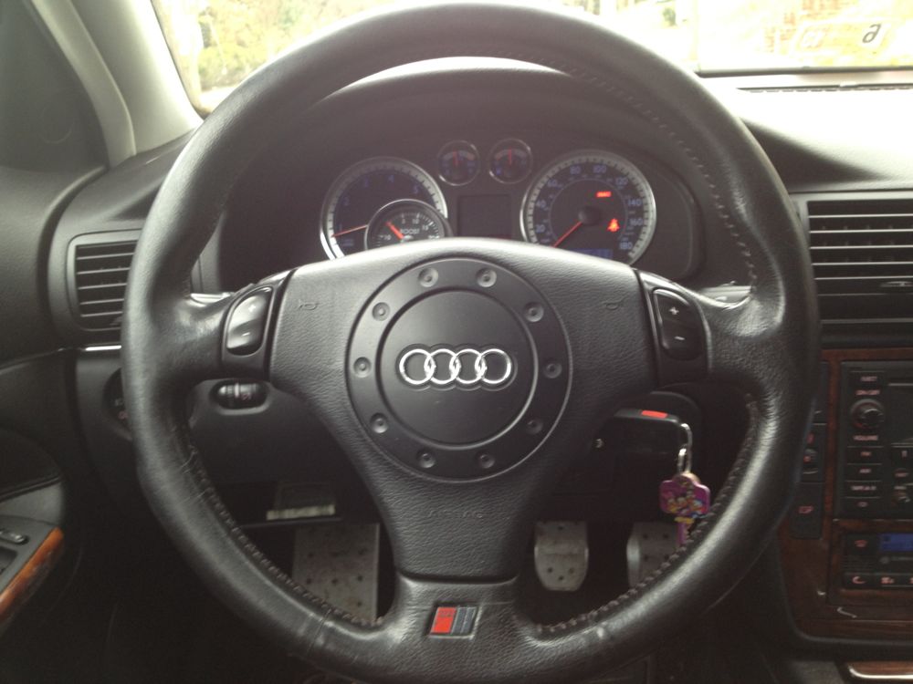
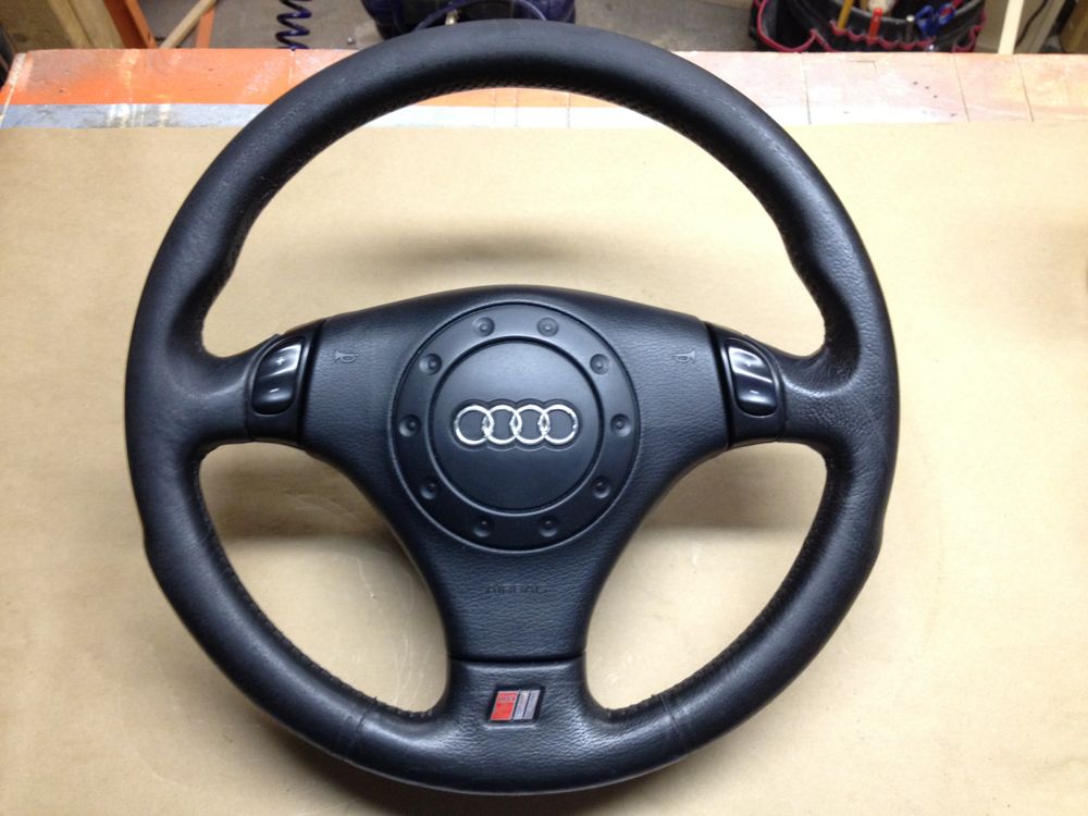
I picked this gorgeous B5 S-Line SW with two spoke-mounted toggle switches (momentary switches under 4 contacts).

Image


I dropped it off today at the cobbler to have the leather restored and resealed.

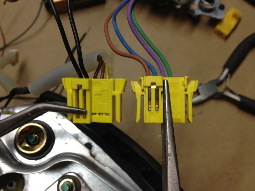
So I started to investigate the setup of the volume and program selection controls on the B5.5 GLX MFSW. I suspected that the button circuits would have variable resistance when closed depending on the button pushed. I disassembled the passenger-side MFSW button module to examine the PCB and map the circuits.

Image


I confirmed that the Volume Up/Dn and Track/Program +/- circuits indeed have distinct resistance values, and I recorded them. FTR, the up toggle on either switch offers a resistance of 3.45KOhms when closed, and the down toggle measures 1.67KOhms when closed. So two wires, two signals that can be easily replicated. The remaining two wires into the passenger-side module were the common power supply (brown) and the backlight LED ground.

So I am pretty jazzed, thinking this may be super easy if the button module on the other side is similarly configured. That would mean that the CAN bus translator could possibly not reside in the MFSW itself, but instead somewhere in the dash further along the harness to the MFSW relay.

Then I opened up the other button module, and was a little deflated:

Image


Image


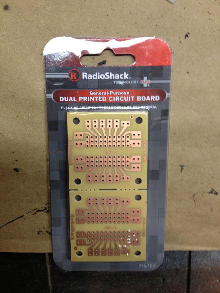
Those clever Germans packaged the CAN bus translator in the Cruise Control button module. Argh. So now I have to move the processor into the dash and configure the four wire harness coming from the S-Line wheel to convince the processor it is getting signals from the MFSW Volume and Track selection switches when I use them. Not to worry, I have mapped out the individual S-Line switches too:

Image


Image


Image


Image


It is actually not going to be that difficult, because the two S-Line PCBs as a pair have nearly identical characteristics to the Volume/Track switch array in the passenger-side B5.5 MFSW button module.

Just thought you might find it interesting. Or maybe nerdy. Or perhaps both. Gotta do something until Tuesday.

:icon_eek: :nerd:
 
#5 · (Edited)
Holy crap... it works!


Turns out you were quite right. The buttons were originally for Tiptronic controls.

UPDATE:

I just went for a test drive with the modified can bus module installed in a slimmed plastic case between the airbag and the steering wheel 12-point hub bolt. I opted to have the left tiptronic +/- toggle control the set/accel and resume cruise control functions and the right tiptronic +/- toggle will control the volume on the Monsoon head unit.

But wait, there's more. I figured out how to mount concealed momentary switches in the back of the left and right spokes so I also have controls for the cruise cancel and the program/track up/down functions on the audio system. I even added a fourth button to restore the steering wheel button backlight on/off function. :nerd:

I have a bit of tidying up to do, and I need to complete the connection for the buttons in the right hand spoke, but the cruise set, accel, resume, cancel and back light buttons are all working like clockwork.

These pictures will probably need some additional explanation, and I need to add some more detail shots of the final modified CAN-Bus module now buried in my S-Line A4 three spoke wheel. For now I leave this gallery of mostly unedited photos:

From my second thread post, you may recall this photo of the CAN bus translator buried in the left hand MFSW button module. This little bugger translates button signals from the other right hand controls and also the horn circuit and sends the information on a CAN bus signal wire for the appropriate modules to handle in the dash:
Image


The LEDs and the switches underneath all have to be removed because they make the assembly too thick to fit in between the hub and the airbag, and I need to replicate the switch functions elsewhere in the assembly. So I removed them. I also removed the remaining momentary switch near bottom center that controls the back light LED on/off relay:
Image


So to replace the MSFW switches I removed from the PCB, I needed to add a number of momentary switches attached to the PCB via wired pairs. I had these in my electronic parts bin from Mouser. They are tiny, but have a nice tactile click feel when depressed:
Image


The original momentary switch actuated by MFSW controls is left, the replacement is right:
Image


To connect the switches, I soldered a series of wire pairs to the PCB switch contacts:
Image


For a little extra protection against pulled wires, I used the holes for the switch mounts to thread the wires through and then twisted the pairs:
Image

Note: this photo shows initial pair connections on the salvaged PCB I collected from a wrecked GLS. It turns out the white connectors on this board were not compatible with my 2004 GLX MFSW harness, so I had to start over and modify my original board.

And I soldered new momentary switches to the leads for the back light on/off relay controller and the cruise cancel button:
Image


I need to add one or two additional photos at this point to describe bridging the LED circuit to attach the Tiptronic toggle back lights to the controller board, and show how the left toggle switches were eventually wired directly to this PCB in place of the two rightmost pairs.


With the PCB mods completed, I needed a safe place for it to live once installed inside the Audi steering wheel. To make a custom fit controller board tray, I sacrificed the module outer case from the scrap MFSW controls I picked a few weeks ago as test fodder. With the steering wheel buttons attached, the case is too deep to fit in the 1/2" deep airspace over the steering wheel hub nut and the airbag module. I just need the PCB tray.
Image


So I used my Dremel and cut off the hunchback part that housed the now unneeded buttons:
Image


With the buttons gone, the tray starts to take shape:
Image


Straightening the irregular edge on the flip side gets the tray under 1cm in thickness:
Image


A little flush sanding the cut off wall stubs cleans things up a bit.
Image


This is a view of the scrap PCB in the newly shaped tray with controller wires going to flush buttons for cruise functions. I later decided to put set accel and resume functions into left tiptronic toggle, so on the real PCB, this wiring is all changed:
Image


The 5-pin connector on the right goes to the clock spring connector. The 7-pin connector on the left is normally bridged to the right MFSW controls for volume and track/program select.
Image


A test fit yesterday to make sure tray would have clearance when the steering wheel is reassembled and the airbag is reinstalled. I added a plastic cover to the tray that fits snugly flush in the tray frame (not pictured here yet):
Image


In each of the left and right spokes, there is a solid steel frame member molded into the more pliable rubber housing. Plenty of room above and below to mount my concealed momentary switches:
Image


Image


The last time these will look pristine from the back:
Image


Image


I threw out an old CRT TV last week but I saved the remote, because I thought the keypad insert might be useful:
Image


Image


Image


With my Dremel, I carefully bored a small hole through the soft rubber housing of the steering wheel back:
Image

Once the starter hole was located, I flipped the wheel over and continued to clean out and shape the hole for the flush mounted button insert:
Image


Image


The rubber housing is tad to thick, so I had to rout out a bit of the inner material so the button would eventually sit flush to the surface of the wheel spoke:
Image


This process shows he preparation of the right spoke, and the hidden buttons will be used for the track selection, so I need two side-by-side:
Image


With the holes bored and the insides mortised a bit to allow the button inserts to lie flush to the outside, this is what the buttons look like form the inside before the momentary switches are installed:
Image


And this is a view from the outside:
Image


Image


I prepped the mortise with contact cement, and then prepped the button inserts:
Image


Image


So this is where excitement took over and I stopped taking pictures for a while. More pics of the button installations and final PCB board configuration in the coming days.

On to solving the harness differences. In the S-line wheel, the horn function and airbag use four of the five terminals in the yellow connector:
Image


Left to right, horn, horn, airbag, airbag. Both functions are simple circuits. The horn circuit is always energized and closes when the horn contacts are touched together, bleating the horn. The airbag circuit is always closed, and is only energized when the airbag module wants the airbag to detonate. Accidentally mixing any of these wires would likely result in an airbag going off. Yikes!
Image


The CAN-Bus MFSW wheel uses the exact same connector, but the wire functions are different. In this side-by-side, the two left wires in each connector are for the airbag. That function is unchanged. The next three wires in the MFSW are respectively the power, ground, and CAN-Bus signal wire:
Image


So the balance of my evening was spent splicing the MFSW harness into the S-Line airbag and horn contacts, and then connecting the left tiptronic toggle to the skinny MFSW module in the newly formed tray, connecting two momentary switches to the module for the cruise cancel and button back light on/off, and then buttoning it up enough to take it for a test spin to make sure I was on the right track.

This photo shows a couple of the wire welds that I did in the harness splicing. In the MFSW wheel, the horn signal is actually sent along the CAN-Bus signal wire, so if the module is not present, it is not going to be an easy task to restore the horn function at all. In the background of this photo, the salvaged PCB sits to the left of the PCB taken directly from the MFSW removed from my 2004 GLX. In this photo, I hadn't yet removed the LEDs and button switches that are soldered to the PCB for cruise and back light control functions.
Image


:lightsaber:
 
#4 ·
I don't think they were shift buttons for the Tip because the wheel came off a 5-speed B5. They are most likely buttons for volume and program selection, they may have also been used in conjunction with the stalk controls to display info in the FIS display.

Whatever the case. The circuits use four wires, one for each control switch, one for the back light LEDs and one for the common ground. My theory is the four wires can be traced through the clock spring ribbon to the steering column and then spliced into there to put the MFSW cruise control module back in line and nobody would be the wiser.

What I haven't tried yet is if the MFSW cruise control module is back on the CAN Bus, will the set/accel buttons on the turn signal stalk work as well. That would be a bonus and keep me from having to install blister switches in the steering column to actuate the appropriate functions on the cruise control module.

I am going back to boneyard tomorrow to pick up an extra MFSW cruise control module and some other steering column parts to tinker with. Like I don't have enough tinkering projects going already. ;)

Have you seen these?

Image


Or these?

Image


Or this?

Image


:rolleyes:
 
#6 ·
Added some missing process pics and reordered them so they make more sense. Still need to complete the DIY step-by-step, hope to wrap it up tonight. :wrench:
 
#8 ·
all this just for a steering wheel. to each their own though i guess.
Ouch! ;)

AFAIK, there is no bolt on multifunction steering wheel available for B5 Audis or B5/5.5/MkIV VWs with the more sporty three-spoke design. I love the feel and appearance of a three-spoke wheel, but I was really missing the steering wheel controls for audio volume and more so, track selection. I could care less about cruise control because I rarely if ever used it. So I hatched a plan to create my own.

So I went from this:
Image


To this:
Image


And I didn't lose one iota of functionality.

:D
 
#13 ·
Oh wow! Check it out, you've got a Disney family key! :lol: ;)

Looks pretty legit though, quite the project for the feature but it's pretty awesome that you got it all figured out. One has to wonder how you keep up with so many miscellaneous projects for your car, LED taillights, spring loaded trunk mechanisms, a supercharger install, Lucas rear brake rebuilds, steering wheel multifunction button adaptations, but I haven't been viewing those threads obviously :rolleye:

Thanks for keeping it interesting and keep up the projects, I enjoy reading through them!
 
#19 ·
I'd need the MFSW relay (if chassis supports) and a MFSW to cannibalize the CAN bus translator board? Any other way would need more conductors in the clock spring I would think.
Yes, only audio controls. I was thinking program/tuner up/down on the left toggle and volume up/down on the right toggle.
If I remember right, there is no harness on the back of my radio where the external radio control signal would be pipped in. (connector I, Green)

http://www.gti-vr6.net/library/hifi/Late_98_Radio.gif

Has anyone here worked on a 99 (no CAN) MFSW and if so, where there more than 5 conductors from the wheel to the clock spring?
I figure a pair for the airbag.
A pair for the horn.
That leaves dimmable lighting feed, data path and ground conductors to be run somehow.

I've seen this writeup, but that is a newer car and he's going the opposite direction.
http://www.passatworld.com/forums/6...ation-base/150638-installing-r32-3-spoke-steering-wheel-multifunction-swap.html

I totally agree with your "once you have it, it's hard to go without" comment. My truck has steering wheel controls and when I get into the Passat, my fingers reach for buttons that aren't there. :rolleyes:
 
#22 · (Edited)
New button inserts installed

I spent an hour or two today getting the button inserts mirrored on the other side (left hand spoke) for the cruise cancel and back light relay switches.

In my earlier post, I had installed the right spoke button inserts for the track selection up and down. I actually pulled those out today and re-cemented them using gasket RTV. It hardens in a bout an hour and remains pliable, and I have almost a full tube of it remaining after my cam cover gasket replacement two weeks ago.

Here is an array of images from the button installs. I'll fill in details and add descriptions later.

I transferred the button hole size and spacing to the back of the left hand spoke with a rubbing from the holes already bored on the right, then I use the Dremel to carefully open the holes and shape them to the button inserts:
Image


Image


Once the second set of button holes were open, I routed out enough materials from the back side to allow the button inserts to stick out the back about .5mm:
Image


With the holes open and symmetrical on both sides, I used little dabs of anthracite RTV to center and secure the inserts in the holes:
Image


Image


Image


Image


I picked this up a Radio Shack to make the button PCBs out of:
Image


I'm still learning the techniques and applications of my SMD rework station, so I scorched on of the PCBs a little, but it was not damaged functionally. I tinned the circuit paths I planned to use and soldered the button switches to the PCBs with theirs centers spread to match the button inserts in the steering wheel:
Image


I then soldered small gauge wire leads to the switches coming up from below through adjacent holes:
Image


In the midst of all this I discovered I had damaged this switch on one of the steering wheel +/- toggles. I had to disassemble it and repair the contact blades. Whew! I thought I was going to have to buy another steering wheel to scrap for just that little switch:
Image


I used a cutting wheel on the Dremel to cut the PCBs to size to fit the button recesses in the spoke arms and position the button switches directly behind the insert centers. I then used RTV to "glue" the button PCBs in position on both arms. I filled the edges on three sides to make sure that the buttons board would not work loose after repeated use over time:
Image


Image


I reinstalled the repaired switch on the right toggle PCB and bridged the resistors on the LED circuits so they would be brighter. There is already a 220 Ohm resistor on the MFSW module PCB circuit for the LED backlights, so the extra resistors on these satellite boards were knocking the brightness down further. I will go back and replace these bridged resistors with 0 Ohm ones once I get some from Mouser, and I may replace the 220 Ohm resistor on the MFSW PCB too because I think the button back lights are still too dim:
Image


With the toggle switches reinstalled, I test fit the modified MFSW module PCB in the tray case I made along with the wires harnesses in progress. I also fitted the PCB tray with a recessed plastic cover I made from an old plastic luggage tag blank:
Image


The switch resistors for the right spoke buttons are on a satellite board that was inside the right spoke MFSW button module. I cut the board down to the essentials needed to process the switch signals and wrapped the mini-board in insulating tape:
Image


Wheel was then ready to install. Here is the wheel on the steering hub in my car before the 12-point fastener is installed. The PCB tray tilts out of the way so the nut can be threaded into the hub and tightened:
Image


Once the nut has been installed and tightened, the PCB tray lies flat in the space directly over it:
Image


The airbag harness is attached to the PCB tray and the clock spring connector:
Image


And then the mini PCB wrapped in electrical tape is tucked into the gap to the right of the clock spring connector and above the metal spoke frame, about midway from hub to RTV secured button PCB on the right.

Airbag was then secured with the torx fasteners from the back and voila!

Cruise control cancel on the left spoke, outside back button, back light relay on the left spoke, inside back button:
Image


Audio track up/down controls on the right spoke back buttons (outside is up/+, inside is down/-)
Image


Original Tiptronic toggles on S-Line wheel are now Cruise Accel/+, Cruise Resume/- on left spoke, Volume Up/+, Volume Down/- on right spoke:
Image


:barmy:

:wrench:
 
#26 ·
Mine may soon be available if I complete a conversion of the R32 wheel I picked last week. ;)

Else I might be able to convert another for $250 plus cost of wheel and airbag ($125-$150). I would pick the sacrificial button modules from a local yard.


Sent from AutoGuide.com App