

Warning: This procedure requires the cutting and soldering of wires. I or anybody on this forum shall not be responsible for any damage you cause. Do this at your own risk!
After much research and the help of a friend who managed to accomplish the install I have finally put together all the information necessary to complete a Multi-Function Steer Wheel (MFSW for short) retrofit. This retrofit is not for the faint of heart but it is well worth it. With these instructions I would estimate about 4-6 hrs to complete it. If anybody has any questions feel free to contact me. I can also help you obtain any of the parts needed. I am also willing to make some wiring harnesses if anybody is interested.
Parts Required:
Tools Required:
So Which Relay do I need?
There are two possible relays that can be installed on these cars. The older version is Relay 452 which works by communicating with the stereo via a communication wire. The newer version is Relay 451 which uses CAN. Now here comes the confusing part: Relay 451 can be programmed to be used as Relay 452 via Vag-Com by changing the soft coding from 0118 (CAN Communication) to 00008 (Non-CAN). Now the way to determine which relay you need is if you have a SINGLE DIN radio then you will need 452 because it does not have CAN. DOUBLE DIN radios will use 451 since they have CAN. If you have a 2001.5 B5.5 like I do then you have the ability to use Relay 451 as the car has CAN but it will be coded as a NON-CAN car because the car still uses a single din radio.
The wiring will differ between 451 and 452 but only in the pins that need to be connected. The pinout for both relays is the SAME. This was a big source of confusion until I understood this.
Now on to understanding the wiring diagrams: To be able to do this you must understand the terminology used. The Bentley wirings diagrams specify the connector/pin # (e.g. T18c/12).
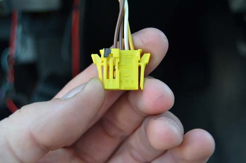
Here is a list of the specified connectors:
![Image]()
- T5b – Clock Spring Connector
![Image]()
The Actual Instructions:
1. Disconnect the Battery. Make sure to write down the mileage if you like to keep track of fuel economy like myself.
2. Remove Lower Knee Panel. Do this by removing the headlight switch, fuse panel, and then the 4 torx that hold it on.
3. Remove the Airbag/Steering Wheel. Refer to other instructions: http://www.passatworld.com/forums/61-b5-information-base/150638-installing-r32-3-spoke-steering-wheel-multifunction-swap.html
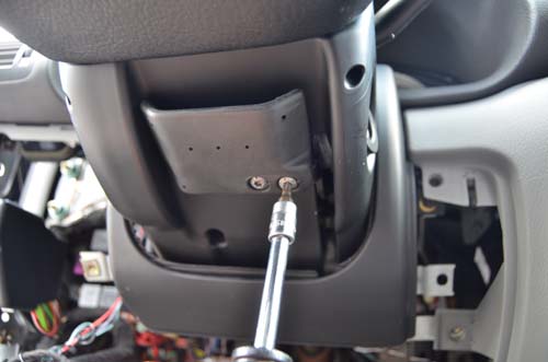
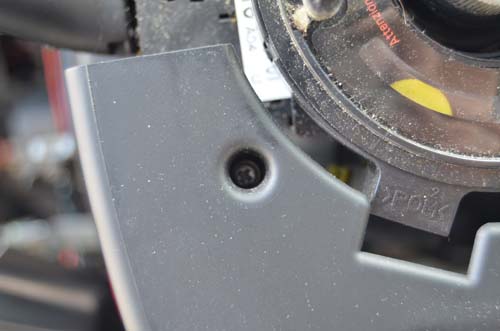
4. Remove steering column clam shell. Do this by removing the torx that hold on the column adjuster. There is one torx and two long phillips on the bottom of the clam shell along with two phillips on the front.
![Image]()
![Image]()
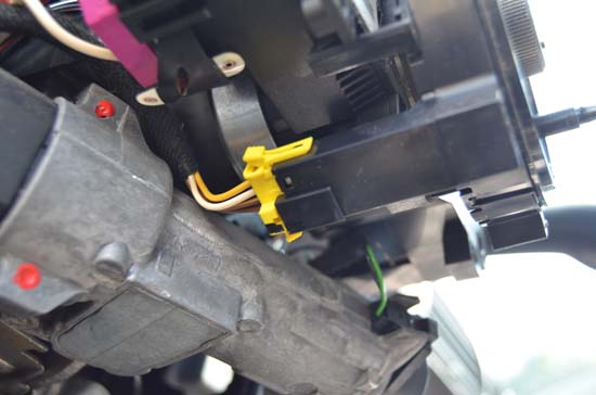
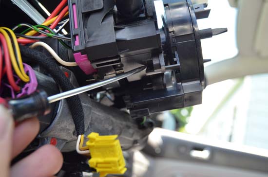
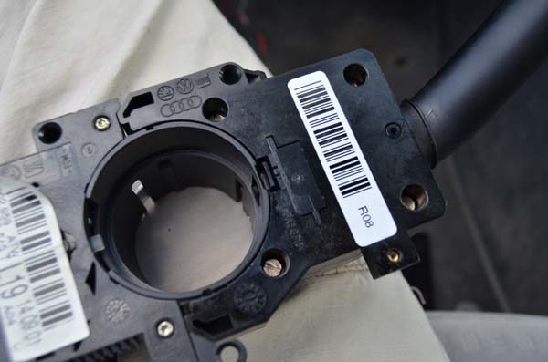
5. Remove Clockspring. It has one connector and three clips holding it in.
![Image]()
![Image]()
![Image]()
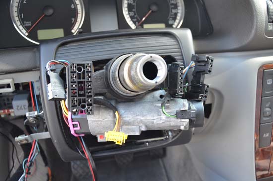
6. Disconnect stalks. Each one has two connectors. Then remove them by loosening the 5mm allen bolt.
![Image]()
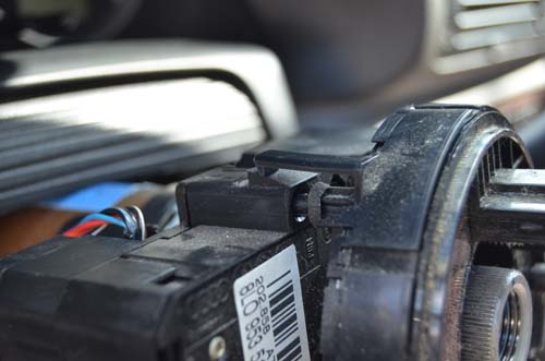
7. Separate the stalks by releasing the pictured clip and sliding them apart.
![Image]()
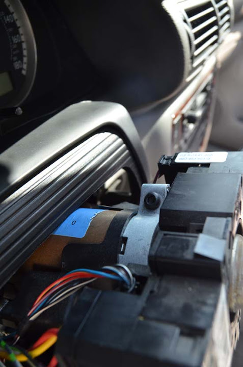
At this point this is what it should look like.
![Image]()
Step 8. (Kinda Long)
At this point you should take a moment and soldering wire extensions on to relay plate. I highly recommend starting at the relay plate and working backwards instead of the other way around. Here are the locations that the relay pins should go to. This information was provided by waldo22 on tdiclub; however it was modified for B5 connections. Disclaimer: Not all the colors match up and that is just fine as long as the pins match. I also ran a wire from the previous Cruise connection instead of running the wires to the ECU. This means that anywhere you see "Wire to T10s/*" means that you cut the wire at the connection and solder a new wire running down to the relay panel.
T18c Pin Location - Color/Strip - Function/Destination
1 - Orange/Brown - CAN Low (Not applicable for Relay 452)
2 - N/A
3 - Orange/Brown - CAN High (Not applicable for Relay 452)
4 - Black/White - Cruise Off Function - Wire into T10s/4
5 - Lavender - REM wire for remote control of NON-CAN radio (Read: SINGLE DIN). Wire into T20/11 on the back of the radio (Green Connector Pin 11). DO NOT wire this for Double DIN.
6 - Green/Purple - Diagnostic K-Wire. Option is either to wire it into T16/7 on the instrument panel wiring harness or pick up from OBD2 port.
7 - N/A
8 - Red/Yellow - Cruise Set Output, Run wire to T10s/3
9 - Brown/Yellow - Dual Tone Horn Relay, Run wire to S1/6. This is the leftmost connector on the bottom relay panel. Cut the original wire at S1/6 and make sure to leave enough to solder in at either end. The wire that has been cut (running into the harness, not connector) runs to T5b/3. This USED to be the horn but with the MFSW it is now the switch power. I wired this end into T18c/12 and then 75x (switched power).
10 - Brown - Ground, connect to any ground connection
11 - N/A
12 - Black/Red - 12V Switched Power, Wire this and T18c/9 into 75x.
13 - Red/Green - 12V Power, connect to fuse 40 OR run an inline fuse.
14 - Red/Grey - Cruise Cancel, Wire to T10s/5
15 - Grey/Blue - Illumination Wire, tap into T3c/3 (Dimmer Switch Connector). NOT needed for Relay 451.
16 - Blue - Cruise Resume, Wire to T10s/2
17 - N/A
18 - Green/White - Data Bus Connection, add wire to T5b/1 (Far right on connector)
Step 9. Install in reverse order.
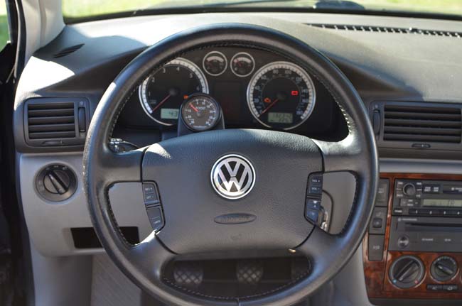
Once you are done it should look like this:
![Image]()
I have attached the necessary wiring diagrams if you are more of a visual person. Don't mind that it is a golf/jetta diagram because they share the wheel, clockspring, turn signal stalks and relay plates with the passats. In essence they share the same electrical systems just with different dimensions.
Resources:
TDIClub Forums - View Single Post - replacing steering wheel with multifunction wheel
replacing steering wheel with multifunction wheel - TDIClub Forums
After much research and the help of a friend who managed to accomplish the install I have finally put together all the information necessary to complete a Multi-Function Steer Wheel (MFSW for short) retrofit. This retrofit is not for the faint of heart but it is well worth it. With these instructions I would estimate about 4-6 hrs to complete it. If anybody has any questions feel free to contact me. I can also help you obtain any of the parts needed. I am also willing to make some wiring harnesses if anybody is interested.
Parts Required:
- Multi-Function Steering Wheel with Airbag
- 5 Pin Clock Spring (All North American B5.5 clock springs will work)
- Multi-Function Steering Wheel turn signal stalk (Only has the on/off for cruise)
- Relay 451 or 452 with relay plate (Read below for which one you need)
- Wiring to clockspring/cruise on turn signal stalk
Tools Required:
- Soldering Iron
- Solder
- Heatshrink
- Stranded Wire (I used 22 gauge wire)
- T25 Torx
- 8mm and 10mm Socket
- Small Flathead to take of Airbag
- 12mm Triple Square Bit OR T55 Torx to take off the Wheel
- Allen Wrenches (I believe it was 5mm)
So Which Relay do I need?
There are two possible relays that can be installed on these cars. The older version is Relay 452 which works by communicating with the stereo via a communication wire. The newer version is Relay 451 which uses CAN. Now here comes the confusing part: Relay 451 can be programmed to be used as Relay 452 via Vag-Com by changing the soft coding from 0118 (CAN Communication) to 00008 (Non-CAN). Now the way to determine which relay you need is if you have a SINGLE DIN radio then you will need 452 because it does not have CAN. DOUBLE DIN radios will use 451 since they have CAN. If you have a 2001.5 B5.5 like I do then you have the ability to use Relay 451 as the car has CAN but it will be coded as a NON-CAN car because the car still uses a single din radio.
The wiring will differ between 451 and 452 but only in the pins that need to be connected. The pinout for both relays is the SAME. This was a big source of confusion until I understood this.
Now on to understanding the wiring diagrams: To be able to do this you must understand the terminology used. The Bentley wirings diagrams specify the connector/pin # (e.g. T18c/12).
Here is a list of the specified connectors:
- T18c – Double Relay Plate for either 451 or 452
- T10s - Cruise Connector on Turn Signal Stalk
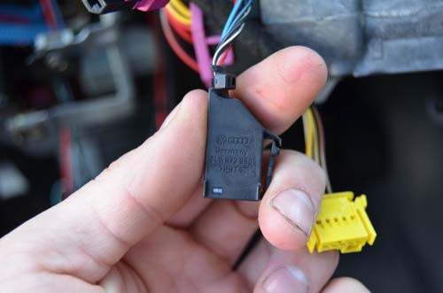
- T5b – Clock Spring Connector
The Actual Instructions:
1. Disconnect the Battery. Make sure to write down the mileage if you like to keep track of fuel economy like myself.
2. Remove Lower Knee Panel. Do this by removing the headlight switch, fuse panel, and then the 4 torx that hold it on.
3. Remove the Airbag/Steering Wheel. Refer to other instructions: http://www.passatworld.com/forums/61-b5-information-base/150638-installing-r32-3-spoke-steering-wheel-multifunction-swap.html
4. Remove steering column clam shell. Do this by removing the torx that hold on the column adjuster. There is one torx and two long phillips on the bottom of the clam shell along with two phillips on the front.
5. Remove Clockspring. It has one connector and three clips holding it in.
6. Disconnect stalks. Each one has two connectors. Then remove them by loosening the 5mm allen bolt.
7. Separate the stalks by releasing the pictured clip and sliding them apart.
At this point this is what it should look like.
Step 8. (Kinda Long)
At this point you should take a moment and soldering wire extensions on to relay plate. I highly recommend starting at the relay plate and working backwards instead of the other way around. Here are the locations that the relay pins should go to. This information was provided by waldo22 on tdiclub; however it was modified for B5 connections. Disclaimer: Not all the colors match up and that is just fine as long as the pins match. I also ran a wire from the previous Cruise connection instead of running the wires to the ECU. This means that anywhere you see "Wire to T10s/*" means that you cut the wire at the connection and solder a new wire running down to the relay panel.
T18c Pin Location - Color/Strip - Function/Destination
1 - Orange/Brown - CAN Low (Not applicable for Relay 452)
2 - N/A
3 - Orange/Brown - CAN High (Not applicable for Relay 452)
4 - Black/White - Cruise Off Function - Wire into T10s/4
5 - Lavender - REM wire for remote control of NON-CAN radio (Read: SINGLE DIN). Wire into T20/11 on the back of the radio (Green Connector Pin 11). DO NOT wire this for Double DIN.
6 - Green/Purple - Diagnostic K-Wire. Option is either to wire it into T16/7 on the instrument panel wiring harness or pick up from OBD2 port.
7 - N/A
8 - Red/Yellow - Cruise Set Output, Run wire to T10s/3
9 - Brown/Yellow - Dual Tone Horn Relay, Run wire to S1/6. This is the leftmost connector on the bottom relay panel. Cut the original wire at S1/6 and make sure to leave enough to solder in at either end. The wire that has been cut (running into the harness, not connector) runs to T5b/3. This USED to be the horn but with the MFSW it is now the switch power. I wired this end into T18c/12 and then 75x (switched power).
10 - Brown - Ground, connect to any ground connection
11 - N/A
12 - Black/Red - 12V Switched Power, Wire this and T18c/9 into 75x.
13 - Red/Green - 12V Power, connect to fuse 40 OR run an inline fuse.
14 - Red/Grey - Cruise Cancel, Wire to T10s/5
15 - Grey/Blue - Illumination Wire, tap into T3c/3 (Dimmer Switch Connector). NOT needed for Relay 451.
16 - Blue - Cruise Resume, Wire to T10s/2
17 - N/A
18 - Green/White - Data Bus Connection, add wire to T5b/1 (Far right on connector)
Step 9. Install in reverse order.
Once you are done it should look like this:
I have attached the necessary wiring diagrams if you are more of a visual person. Don't mind that it is a golf/jetta diagram because they share the wheel, clockspring, turn signal stalks and relay plates with the passats. In essence they share the same electrical systems just with different dimensions.
Resources:
TDIClub Forums - View Single Post - replacing steering wheel with multifunction wheel
replacing steering wheel with multifunction wheel - TDIClub Forums
")